|
|
|
 |
|
|
|
|
|
 |
| Related products |
 MPS-Tester Multi-port Vector Network Analysis System
MPS-Tester system expands 2-port Vector Network Analyzer to 4 / 8 / 12 /24 or more ports for accurate vector network analysis on multi-port RF / Microwave components, up to 40GHz.
MPS-Tester system consists of MPS (Multi-Port Switch Matrix), 2-port VNA, and system software.
Our proprietary Multi-port Calibration Algorithm significantly improves the system's accuracy for testing multi-port components up to 40GHz.
The system, as an ideal substitute for expensive 4-port and 8-port VNA, is a cost-effective test tool for testing multi-port DUT, such as Smart Antennas, Base Station Diplexers, Directional Couplers, Hybrid Couplers, Power Combiners / Splitters, Circulators, and other multi-port RF / Mirowave components and modules. MPS-Tester Multi-port Vector Network Analysis System
MPS-Tester system expands 2-port Vector Network Analyzer to 4 / 8 / 12 /24 or more ports for accurate vector network analysis on multi-port RF / Microwave components, up to 40GHz.
MPS-Tester system consists of MPS (Multi-Port Switch Matrix), 2-port VNA, and system software.
Our proprietary Multi-port Calibration Algorithm significantly improves the system's accuracy for testing multi-port components up to 40GHz.
The system, as an ideal substitute for expensive 4-port and 8-port VNA, is a cost-effective test tool for testing multi-port DUT, such as Smart Antennas, Base Station Diplexers, Directional Couplers, Hybrid Couplers, Power Combiners / Splitters, Circulators, and other multi-port RF / Mirowave components and modules.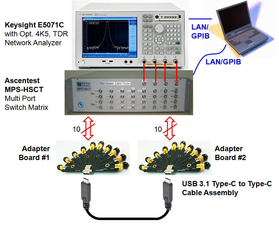 HSCT USB4 Type-C Cable Test System
HSCT-C is dedicated fully automatic test system for USB3.1 Type-C cables. HSCT system is built upon the platform of Ascentest HSCT High-Speed Cable Test System. The system is based on the functions of Keysight E5071C (Opt. 4K5, TDR) and Ascentest MPS-HSCT Multi-Port Switch Matrix. The system automatically and accurately tests the Frequency & Time Domain parameters for USB3.1 Type-C cable assemblies, which greatly speeds up the tests and lowers the test cost. HSCT USB4 Type-C Cable Test System
HSCT-C is dedicated fully automatic test system for USB3.1 Type-C cables. HSCT system is built upon the platform of Ascentest HSCT High-Speed Cable Test System. The system is based on the functions of Keysight E5071C (Opt. 4K5, TDR) and Ascentest MPS-HSCT Multi-Port Switch Matrix. The system automatically and accurately tests the Frequency & Time Domain parameters for USB3.1 Type-C cable assemblies, which greatly speeds up the tests and lowers the test cost. OMTS Optical Transceiver Module Test System
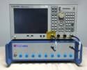
OMTS (Optical transceiver Module Test System) is based upon Ascentest MPS 4x16 Multi-Port RF/uWave Switch Matrix and Ascentest’s proven automatic test platform, implementing the measuring power of Optical Power Meter, Optical Attenuator, Wide-band Oscilloscope, BERT and DC Power Supply, to automatically perform the full 4-channel test for the 40Gbps QSFP+ Optical Transceiver Modules, up to 40GHz. OMTS Optical Transceiver Module Test System
OMTS (Optical transceiver Module Test System) is based upon Ascentest MPS 4x16 Multi-Port RF/uWave Switch Matrix and Ascentest’s proven automatic test platform, implementing the measuring power of Optical Power Meter, Optical Attenuator, Wide-band Oscilloscope, BERT and DC Power Supply, to automatically perform the full 4-channel test for the 40Gbps QSFP+ Optical Transceiver Modules, up to 40GHz.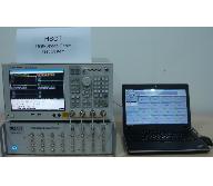 HSCT High-Speed Cable Test System
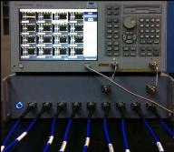
HSCT system is based on the functions of Agilent E5071C (Opt. TDR) and Ascentest MPS-HSCT Multi-Port Switch Matrix. The system automatically and accurately tests the Frequency & Time Domain parameters as well as Eye Diagram for high speed cables up to 100Gbps, such as QSFP28/QSFP+/SFP+/MiniSAS/HDMI, etc. HSCT High-Speed Cable Test System
HSCT system is based on the functions of Agilent E5071C (Opt. TDR) and Ascentest MPS-HSCT Multi-Port Switch Matrix. The system automatically and accurately tests the Frequency & Time Domain parameters as well as Eye Diagram for high speed cables up to 100Gbps, such as QSFP28/QSFP+/SFP+/MiniSAS/HDMI, etc.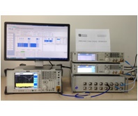 AT890 Compliance Test System for 2.4GHz & 5GHz Wireless Devices
Ascentest Releases AT890 Test System for EN 300 328 V1.8.1 & EN 301 893 V1.7.1 on Sep. 1st, 2014.
AT890 systetm is accurate, convenient, flexible, and cost-effective test tool for Test Labs and Wireless Manufacturers to validate 2.4GHz & 5GHz devices according to the new standards. AT890 Compliance Test System for 2.4GHz & 5GHz Wireless Devices
Ascentest Releases AT890 Test System for EN 300 328 V1.8.1 & EN 301 893 V1.7.1 on Sep. 1st, 2014.
AT890 systetm is accurate, convenient, flexible, and cost-effective test tool for Test Labs and Wireless Manufacturers to validate 2.4GHz & 5GHz devices according to the new standards.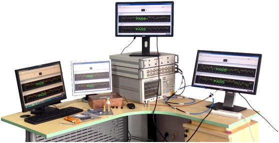 VMNA (Virtual Multi-port Network Analyzer) Test System
VMNA system is built upon Ascentest high-speed solid-state RF Switch Matrix (100MHz ~ 8GHz), which expands a 2-port Vector Network Analyzer to 8-port or 16-port Vector Network Analysis System.
Due to the system’s ultra high-speed switching and sweeping measurement, all the operators at the 16 ports virtually feel like they are using that single 2-port Vector Network Analyzer exclusively!
This is why this system is named as “Virtual Multi-port Network Analyzer”, or VMNA as abbreviation. VMNA (Virtual Multi-port Network Analyzer) Test System
VMNA system is built upon Ascentest high-speed solid-state RF Switch Matrix (100MHz ~ 8GHz), which expands a 2-port Vector Network Analyzer to 8-port or 16-port Vector Network Analysis System.
Due to the system’s ultra high-speed switching and sweeping measurement, all the operators at the 16 ports virtually feel like they are using that single 2-port Vector Network Analyzer exclusively!
This is why this system is named as “Virtual Multi-port Network Analyzer”, or VMNA as abbreviation.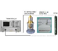 AT105 EM Shileding/Absorbing Material Test System
AT105 Electroagnetic Wave Shileding/Absorbing Material Test System consists of Agilent ENA/PAN/PNA-L Network Analyzer and Ascentest customized accessories and software.
The system automatically tests the following key parameters of the MUT(Material Under Test): Shielding Effect, Permeability/Permittivity, Reflection Loss/Attenuation, Power Loss. AT105 EM Shileding/Absorbing Material Test System
AT105 Electroagnetic Wave Shileding/Absorbing Material Test System consists of Agilent ENA/PAN/PNA-L Network Analyzer and Ascentest customized accessories and software.
The system automatically tests the following key parameters of the MUT(Material Under Test): Shielding Effect, Permeability/Permittivity, Reflection Loss/Attenuation, Power Loss.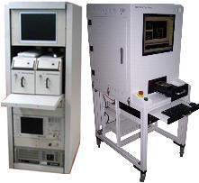 AT500 Wireless Terminal Production Test Systems
Wireless Terminals, such as mobile phones, smart phones and PADs, are integrating more and more functions including Wireless Technologies such as 2G/3G/WiFi/Bluetooth/A-GPS/FM, etc.
However, the product's life cycle is becoming shorter and shorter, with much more competition and less profit margin, while the labor cost of production operators is rising sharply.
Therefore, the wireless terminal manufacturers are pushing to reduce production cost even more imperatively.
Ascentest AT500 Series Production Systems are the right solutions to those needs for production cost reduction without compromising product quality, by implementing production automation and informatization, making full use of expensive instruments and optimizing production procedures. AT500 Wireless Terminal Production Test Systems
Wireless Terminals, such as mobile phones, smart phones and PADs, are integrating more and more functions including Wireless Technologies such as 2G/3G/WiFi/Bluetooth/A-GPS/FM, etc.
However, the product's life cycle is becoming shorter and shorter, with much more competition and less profit margin, while the labor cost of production operators is rising sharply.
Therefore, the wireless terminal manufacturers are pushing to reduce production cost even more imperatively.
Ascentest AT500 Series Production Systems are the right solutions to those needs for production cost reduction without compromising product quality, by implementing production automation and informatization, making full use of expensive instruments and optimizing production procedures.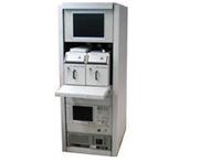 AT510 RF Test System
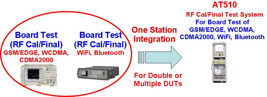
AT510 is RF Calibration / Final Test System for Production of Wireless Terminals, such as mobile phones, smart phones and PADs, etc.
The system implements Non-Signaling test method to improve production efficient for Bard Test of 2G/3G/WiFi/Bluetooth/A-GPS/FM, etc.
AT510 system supports both old and new models of instruments, to increase the utilization of the expensive test equipment, and improve the flexibility for customer’s production investment plan, such as instruments rental.
AT510 system reduces the cost of production not only by improving efficiency, but also by optimizing test procedures, stabilizing the product quality, and reducing the need for operators in production lines.
AT510 system can be controlled by Ascentest PIMS (Production Information Management System) for data collection and production / factory management (Shop Floor Management), to upgrade the production management level. AT510 RF Test System
AT510 is RF Calibration / Final Test System for Production of Wireless Terminals, such as mobile phones, smart phones and PADs, etc.
The system implements Non-Signaling test method to improve production efficient for Bard Test of 2G/3G/WiFi/Bluetooth/A-GPS/FM, etc.
AT510 system supports both old and new models of instruments, to increase the utilization of the expensive test equipment, and improve the flexibility for customer’s production investment plan, such as instruments rental.
AT510 system reduces the cost of production not only by improving efficiency, but also by optimizing test procedures, stabilizing the product quality, and reducing the need for operators in production lines.
AT510 system can be controlled by Ascentest PIMS (Production Information Management System) for data collection and production / factory management (Shop Floor Management), to upgrade the production management level. |
| |
| Product features and technical data: |
| System overview |
AT510 is RF Calibration / Final Test System for Production of Wireless Terminals, such as mobile phones, smart phones and PADs, etc.
The system implements Non-Signaling test method to improve production efficient for Bard Test of 2G/3G/WiFi/Bluetooth/A-GPS/FM, etc.
AT510 system supports both old and new models of instruments, to increase the utilization of the expensive test equipment, and improve the flexibility for customer’s production investment plan, such as instruments rental.
AT510 system reduces the cost of production not only by improving efficiency, but also by optimizing test procedures, stabilizing the product quality, and reducing the need for operators in production lines.
AT510 system can be controlled by Ascentest PIMS (Production Information Management System) for data collection and production / factory management (Shop Floor Management), to upgrade the production management level. |
| Function characteristics |
1. Delivered system designed based on Ascentest’s years of experience in Test & Measurement industry, in light of the current trends of wireless terminal products and industry environment.
2. Non-Signaling Test Method for higher efficiency.
3. Increases production efficiency, while reduces needs for production operators.
4. Modular and flexible hardware and software platform.
5. Compatible with instruments from different vendors.
6. Compatible with Ascentest PIMS (Production Information Management System).
AF5101 Automatic Shield Box Specifications (Pneumatic):
1. Isolation >60dB (800MHz ~ 6GHz)
2. Automatic Control: Pneumatic Control via RS232 Serial Port
3. Manual Control: Buttons for IN/OUT/LOAD, Emergency Stop
4. Air Pressure: 455~500kPa, Tunable Action Speed
5. Power Supply: +24VDC, Max. 1.6A
6. RF Connectors: 6 on Rear Panel for Testing, 1 on Front Panel for Calibration
7. Fixture(Jig): Replaceable & Customizable
AT510-RFIF RF Switch Box Specifications:
1. Frequency Range: DC~3GHz/18GHz
2. Max Power >10W (Cold Switching: RF Signal OFF before Switching)
3. Port VSWR <1.20, typ. 1.15 (<3GHz)
4. Isolation Between Ports >140dB (<3GHz)
5. Insertion Loss <0.5dB, typ. 0.3dB (<3GHz)
6. Switch Time of Single RF Relay <15ms
7. RF Switch Box Overall Switch Time <50ms
8. Switching Cycle (Cold Switching) >1 million, optional >5 million
9. Control Port: RS232 Serial Port (Simplified Command Set) |
| |
|
| |
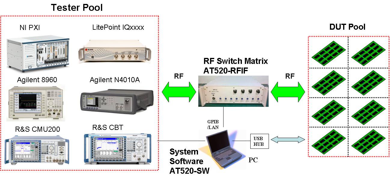
| System structure |
Basic System Concept:
Double-DUT Structure #1:
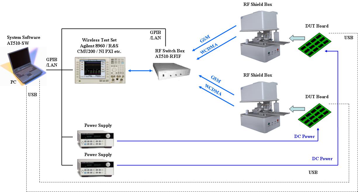
Double-DUT Structure #2:
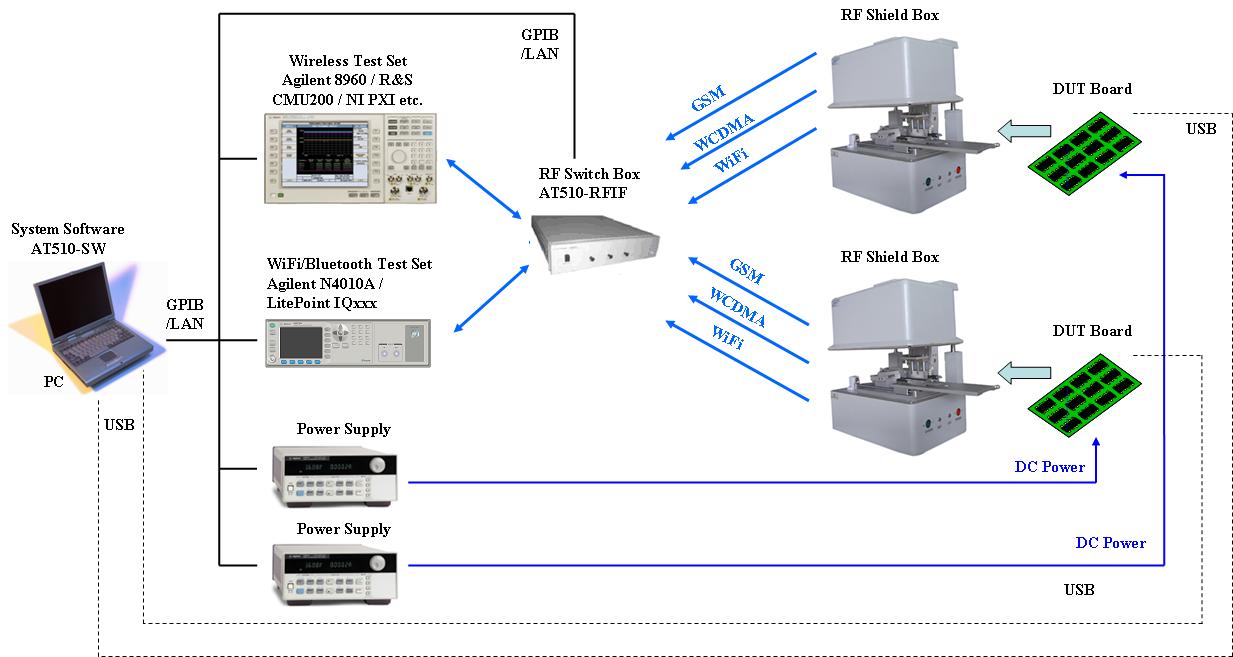
Multiple-DUT Structure:
|
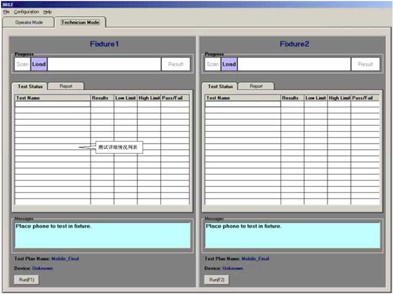
| Software structure |

|
| More |
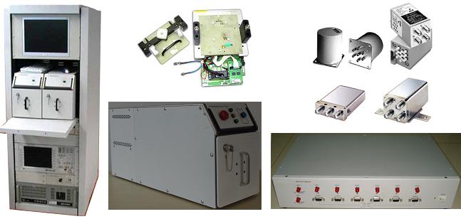
System Photos:
AT510 System, AF5101 RF Shield Box & AT510-RFIF RF Switch Box
|
| Order information( Contact us) |
| AT510 RF Test System |
| |
|
|
|